


SOLID EDGE
- Overview
- Syllabus
- Course Material
- Duration
- Projects
- Certifications
Solid Edge is a 3D CAD, parametric feature and synchronous technology solid modeling software.
It provides solid modeling, assembly modelling and 2D orthographic view functionality for mechanical designers.
The ordered modeling process begins with a base feature controlled by a 2D sketch, which is either a linear, revolved, lofted, or swept extrusion. Each subsequent feature is built on the previous feature.
The Direct modeling features allows the user to change model geometry/topology without being hindered by a native model's existing—or an imported model's lack of—parametric and/or history data.
The software combines direct modeling with dimension driven design (features and synchronously solving parametrics) under the name "Synchronous Technology". Parametric relationships can be applied directly to the solid features without having to depend on 2D sketch geometry, and common parametric relationships are applied automatically.
Unlike other direct modeling systems, it is not driven by the typical history-based modeling system, instead providing parametric dimension-driven modeling by synchronizing geometry, parameters and rules using a decision-making engine, allowing users to apply unpredicted changes.
Synchronous Technology has been integrated into Solid Edge and another Siemens commercial CAD software, NX, as an application layer built on the D-Cubed and Parasolid software components
Syllabus
Introduction
Sketcher environment
Constraints
Part Modeling
Shapes
Solid editing
Reference elements
Multi body publish
Surface environment
Key point
Derived curves
Modify surfaces
Sheet metal environment
Cut out
Bend Unbend
Assembly environment
Create part in place
Standard mates
Assembly Features
Drafting
View wizard
Drawing views
Dimensions and annotation.
Course Material
Duration
100 Hours + Project Training
Student Projects


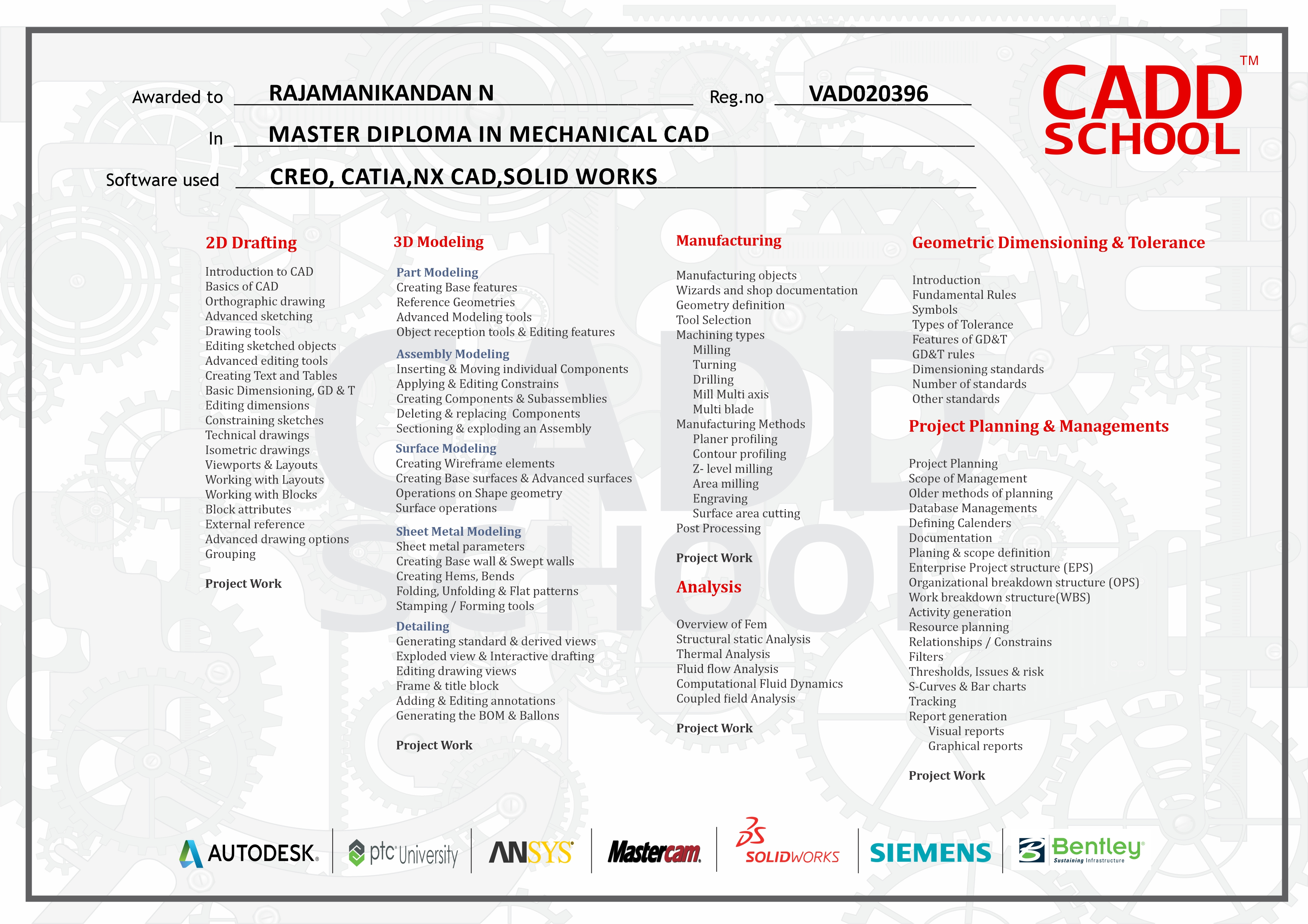
Caddschool Certification
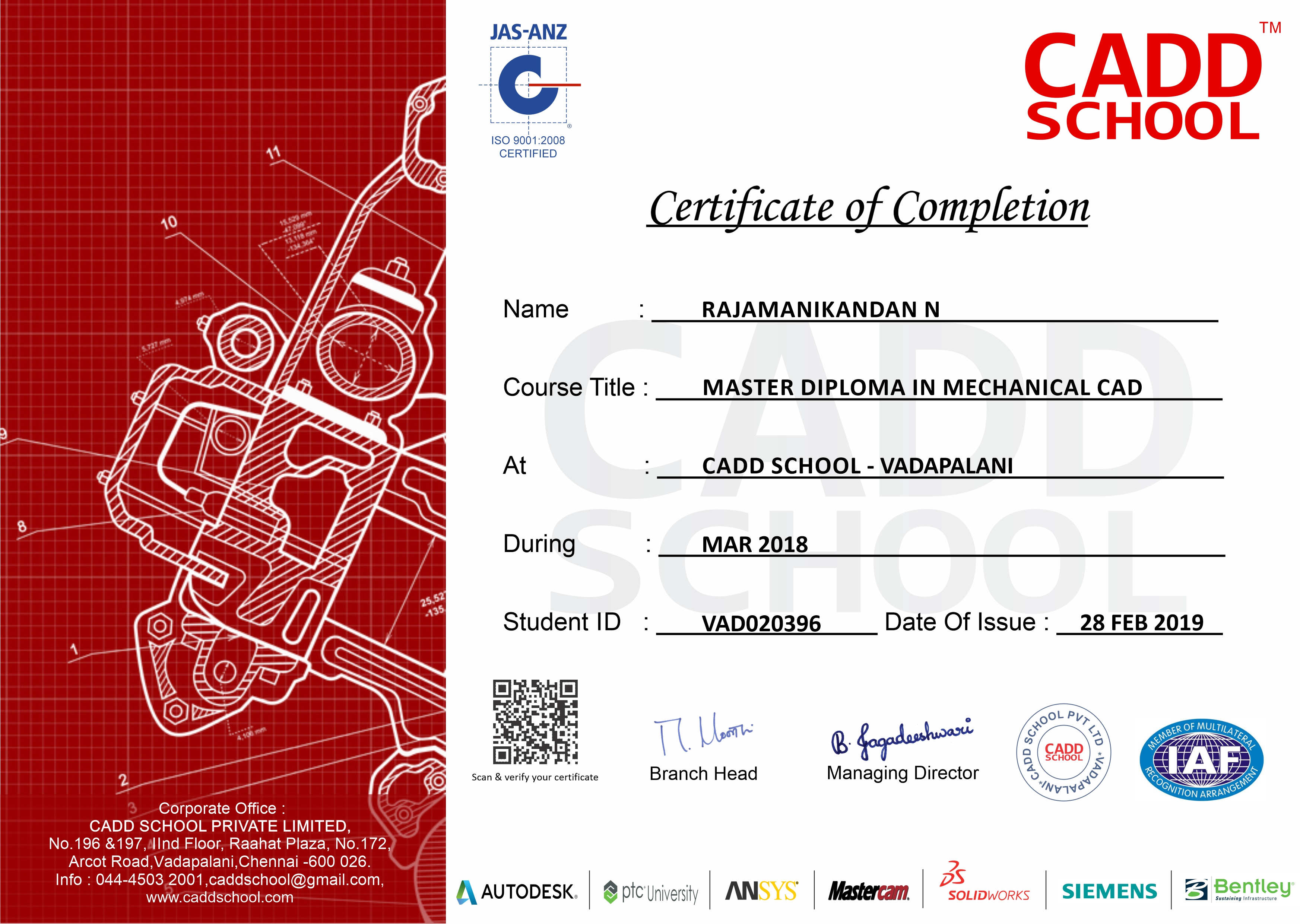
Caddschool Certification
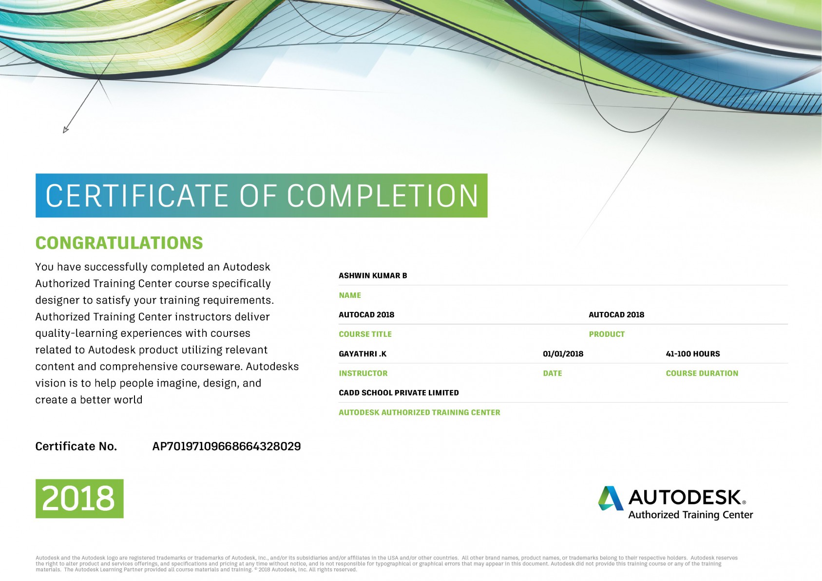
International Certification
Enquiry
MECHANICAL COURSES
